Telephone Science Experiment
You can make a working model of
Alexander Bell’s Liquid Transmitter
Shortly after his successful tuning fork experiment, Alexander Bell put his plans in motion for the final experiment -- transmitting the human voice over a telegraph wire. This is the experiment that gave us the world’s most historic phone call, “Mr. Watson come here. I want to see you.”
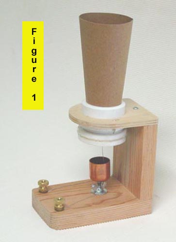
You can duplicate this experiment by building a model of the liquid transmitter similar to the one Bell used for that call. See Figure 1. You can also see a sketch of Bell’s actual instrument at www.antiquetelephonehistory.com. If you have performed the previous experiment (Alexander Bell’s Famous Tuning Fork Experiment), you will have a good idea of how a liquid transmitter works.
.
In a liquid transmitter a short length of wire takes the place of the tuning fork. One end of this wire is attached to a flexible, drum-like membrane. This membrane, when vocal sounds are directed at it, will vibrate just like the tuning fork did. The other end of the wire is adjusted to just barely make contact with a small cup of vinegar (use 5% white vinegar straight from the bottle). Although Bell used a water/acid solution as the liquid, vinegar will perform a similar function. As the voice-driven membrane causes the wire to advance and retreat into the liquid, ever so slightly, the circuit resistance will alternately increase and decrease in perfect step with those vocal sounds. And the resulting alternating current will reproduce the original sounds in a listening or recording device.
The following list of parts and photos suggest one way to make a liquid transmitter. The only requirement is that you must be able to adjust the vinegar cup so that the vibrating wire just makes contact with the vinegar. Other than this, as long as you understand the principle of operation, you can modify the design as you see fit or to utilize whatever materials you may have available. In the model shown, most of the components where obtained from Sears Hardware and Radio Shack, although any comparable source would do as well. The battery can be between 3 and 6-volts; higher voltages can cause unwanted “gassing” on the vibrating wire.
Bell, in his original model, used thin parchment (called gold-beater’s skin) for the vibrating membrane. In lieu of this, you can use “fake parchment” by employing certain types of plasticized paper such as found in some cereal or cracker boxes (e.g., Zesta Saltine or Ritz). It should not stretch, as plastic films do. Later, you will be glueing the vibrating wire to this material. However, certain glues (e.g., model airplane glue and Elmer’s glue) may not adhere well to this material. Try, for instance, contact cement, “crazy glue” or vinyl cement, well dried, to see which works best.
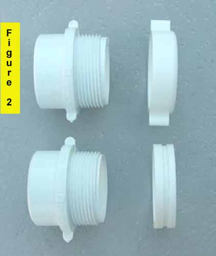
If you use the components listed, you will have to do two modifications. First, the 1-1/4 to 1-1/2 Male Trap Adaptor will have to be altered as shown in Figure 2, which shows the as-purchased and the modified form. The modification entails cutting the two ears off of the adjustable nut, reducing its length by approximately 1/8 inch (so it will thread fully onto the mating part), and cutting an approximately 1/8 inch wide by 1/16 inch deep groove around the outer surface, as shown. This groove will be used to secure the fake parchment. If you have access to the school shop or maintenance department, these modifications can be easily done in a few minutes.
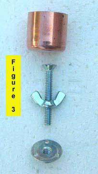
The second modification requires that the head of the 1-1/4 inch, flat-head screw be soldered to the bottom of the 3/4 inch copper cap. See Figure 3. If you first put a thin solder film on the copper cap and also on the screw head, they can then be easily “sweated” together. This assembly, with the locking wing nut, will eventually thread into the “T” nut, thus forming the adjustable vinegar cup.
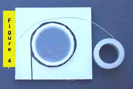
To assemble the fake parchment to the modified Trap Adaptor, make a “stretcher” from a scrap piece of 1/8 inch thick Masonite or cardboard, as shown in Figure 4. Make the hole about an 1/8 inch bigger than the modified adaptor. Cut a piece of fake parchment about 3 inches in diameter and lay it on top of the adaptor. Next, press down all the way with the stretcher to stretch the parchment across the adaptor. Secure the parchment by wrapping a piece of 24 gauge bare bus bar wire around the parchment and forcing it into the groove in the adaptor. Twist the wire to retain it and then trim off the excess wire and parchment. In the final assembly, the parchment will be given the necessary drum-like tautness by turning the adaptor nut on its mating part.
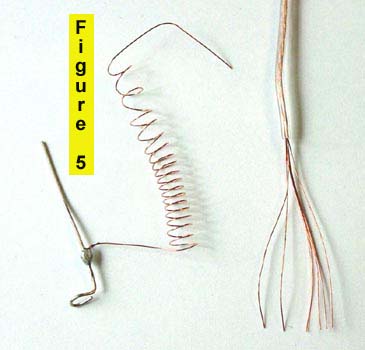
The last assembly is the vibrating wire with its flexible lead. Cut a piece of 24 gauge bare bus bar wire approximately 1-1/4 inches long and bend one end into a small “eye” as shown in Figure 5. This is the end that will be glued to the center of the parchment. This wire must be as free as possible to vibrate by using a “coiled” lead. To make this lead, take a 12-inch piece of ordinary lamp cord or speaker cable and strip off all the insulation. There will usually be about seven strands of fine wire. Take just one strand and coil it around an 1/8 dowel rod, leaving an inch on either end. Solder this coiled lead to the vibrating wire as shown in Figure 7.
Assemble the membrane adjusting nut onto the mating trap adaptor and turn the nut down enough so that the parchment is just beginning to become taut. A final tightening will he made shortly before the instrument is used. Glue the vibrating wire to the center of the parchment, as shown in Figure 7.
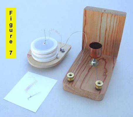
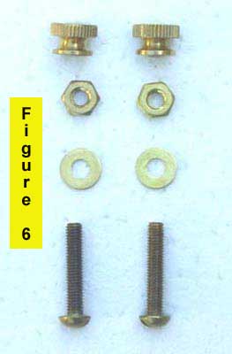
The frame for the instrument is evident from the pictures. Install the binding posts (Figure 6) and the “T” nut in the base. The “T” nut must be directly under the center of the vibrating wire attached to the parchment membrane. Place a piece of bus bar wire under the “T” nut and connect it to one of the binding posts. Connect to the other binding post another wire long enough to reach the coiled lead on the vibrating wire. The connections are shown in Figure 7. The final step is to fashion a cone from light cardboard, as in Figure 1, such that it will fit snugly above the parchment membrane.
CALLING MR. WATSON
Prior to using the transmitter, be sure to tighten the membrane adjusting nut approximately 1/4 of a turn to put some drum-like tension on the membrane. Do not over tighten (when finished, un-tighten the nut). Add the vinegar to the adjustable copper cup (an eye-dropper helps), then adjust the copper cup so that the vinegar just makes contact with the wire on the membrane. You can demonstrate the transmitter two ways: (1) by actual voice transmission, or (2) by recording the output into a tape recorder. The first requires two people and a pair of wires long enough to locate the listener out of hearing range of the speaker. Earphones, or even an old telephone receiver, can serve as the listening device. Connect the transmitter, 6-volt battery and receiver in a simple series circuit. Liquid transmitters deliver fairly clear speech but are somewhat lacking in volume. However, what you hear will be pretty much what Thomas Watson heard that afternoon of March 10, 1876.
The second demonstration method is perhaps the easiest and most convenient. By directing the output into the microphone jack of a tape recorder, one person can speak and then listen to the results with minimum effort. This will require a suitable microphone plug and cable, to which has been added a resistor (typically 1,800-4,700 ohm) across the microphone input. Connect the transmitter, battery and tape recorder together in a simple series circuit as before.
PARTS LIST
Qty. Description Part No.
1 Tee Nut, 10-24, brad type 2510-K
2 Knurled nut, 10-32 856-L
2 Flat washer, No. 10 1295-M
2 Screw, RH, 10-32 x 1 2041-M
2 Nut, hex, 10-32 2045-R
1 Nut, wing, 10-24 658-C
1 Screw, FH, 10-24 x 1-1/4 H100245
1 Cap, copper, 3/4
1 Male Trap Adaptor 1-1/2 to 1-1/4
Written and photographed by Mr. Ed Evenson 2002, author of The Telephone Patent Conspiracy of 1876
Please note: The science in this exercise is correct and this "phone" does work if all of the adjustments and tensions are right. Some report that they have not heard speech while others have had great success. The sound heard will not be really clear nor loud, just as it was with Bell and Watson.
New phone technology, such as Vocalocity Hosted PBX is available for home and business uses.