The introduction of the 425A network in the early 1950s marked the end of the self-contained Western Electric 3 slot payphone (at least for a while), because the network was too large to fit in the phone.
If youre familiar with any of the Western or Northern 200 series or QSD-3A payphones, you know they must be used with a 685A subset. For those readers who are civilians, a 685A subset is a separate box that contains a bell and a 425A network. A 425A network is an assembly that electronically matches the audio components in the payphone to the telephone line.
Modified 200 series payphones for home use that dont need subsets, have been on the market for years. To make these phones self-contained, coin relays, hoppers and wiring were removed to make room for networks and ringers.
Apparently, this is fine with the general public. They want a payphone that functions and has the look, for their family room. As a collector, I feel any change made to a phone is unacceptable.
___________________
The Story
The following is detailed information for wiring a modern, printed circuit version of a 425A network into any unmodified Western or Northern Electric 200 series or QSD-3A payphone. The 425A network takes the place of the outboard subset.
This isnt rocket science. Its a basic, simple, neat and inexpensive way of making the phones in your collection work without destroying their authenticity. The added components are sitting in the phone. They arent screwed to, glued to, or taped to anything. They can be removed in less than a minute by disconnecting seven wires.
____________________
The Network
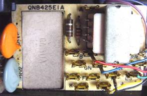
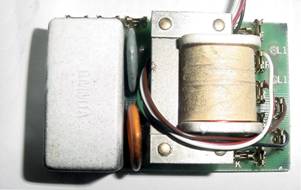
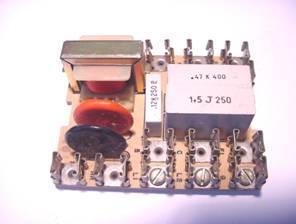
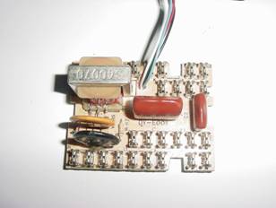
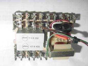
Many companies made printed circuit board versions of the 425A network. Fig.1 shows a few Ive used. Theyre all well built, reliable and readily available.
The two networks in the top row are from Northern Telecom Contempra phones. The networks in the second row were made by ITT, for use in their version of the 500 and 2500 series phones.
The ITT units are my favorite, because theyre a perfect fit for an insulated enclosure I use. ITT made several versions of these with different board layouts and part numbers. Most are stamped 427 or 1427. Theyre all the same size and in this application, electrically identical.
Regardless what network you use, the terminal designations will be the same. Youll probably want to use a standard modular cord to connect the phone to the line. If your junk box is limited, I can recommend a source for these parts. Well talk about that later.
Fig. 1
____________________
Wiring the Network
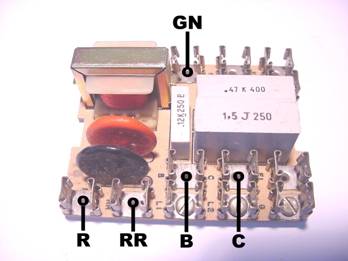
Two versions of ITT boards with harnesses connected are shown in Figs. 2a and 2c. The wires are soldered to terminals B, R, C, RR and GN (see Fig. 2b). The lengths given are for models 233G, 234G*, 210G and 212G payphones.
Solder the wires to the terminals on either side of the pc board. Electrically it makes no difference. Refer to Fig. 3c. If you need a source of wire, well talk about that also.
These are the wire lengths:
B, R, C = 23 inches RR = 16 inches GN = 14 inches
Fig. 2a Fig. 2b
Fig. 2c ____________________
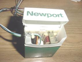
Packaging the Network
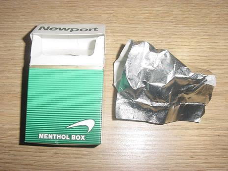
If your phone is a post-pay Western 210G, 212G or Northern QSK-3A, any coins you put in the phone will fall into the coin can. Since the network is also in the can, it must be insulated from the coins. After exhaustive research, I found an enclosure for the network. Its shown in Fig. 3.
Note that it comes standard with RF shielding. In this application I didnt feel the shielding was necessary, so it was tossed in the trash (where it came from originally).
Im not sure this part conforms to Bell System standards. However, Im absolutely sure the Surgeon General doesnt care, one way or the other.
Fig. 3Hey, whatever works!
____________________
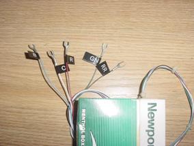
The Completed Network
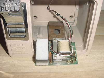
Fig. 4a shows the network installed in the enclosure. The wires run through a hole thats punched in the side of the box. Then the box is taped closed.
Fig. 4b is the completed assembly with the wires labeled and lugged (optional).
Once again, the lengths are:
B, R, C = 23 inches RR = 16 inches GN = 14 inches
Fig. 4a Fig. 4b
____________________
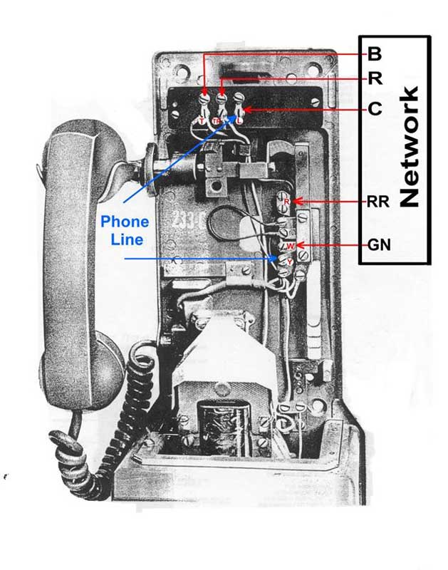
Making It Simple
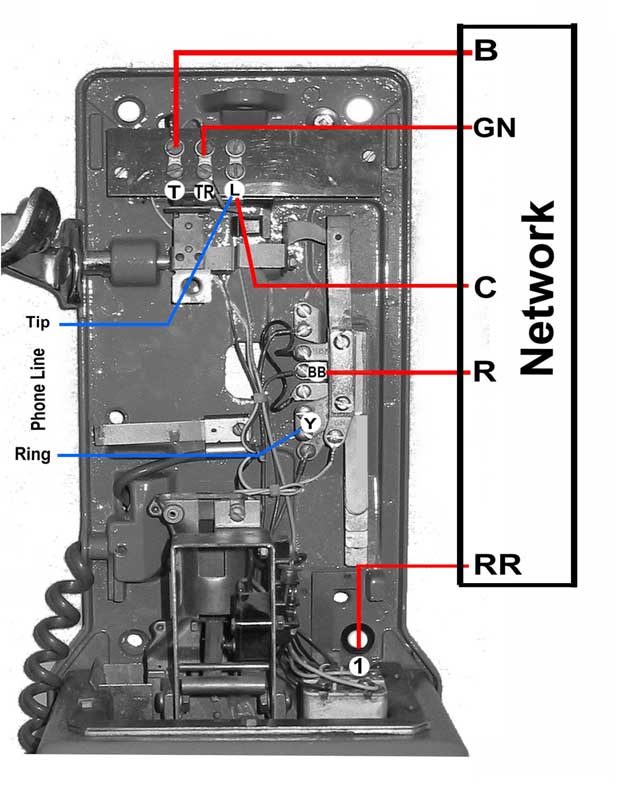
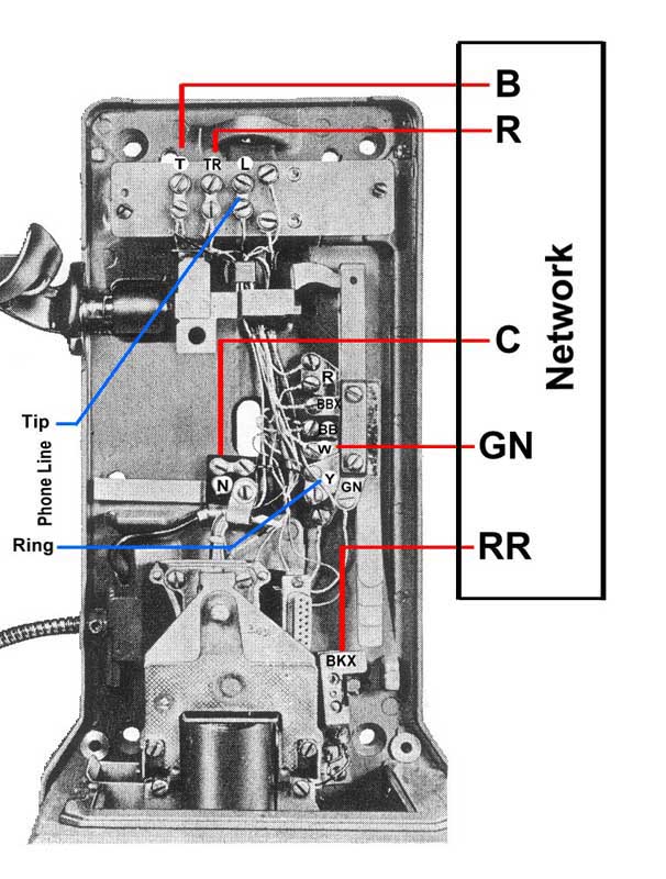
Fig. 5 is a simplified diagram for connecting the completed assembly to a post-pay Western 210G or 212G, and a pre-pay 233G or 234G*. Its also correct for any Northern Electric equivalents.
Detailed installation instructions for these and other models are given below.
Fig. 5 ____________________
Installing the Network
The following photos show networks installed in representative samples of each type of three slot payphone that was manufactured. Differences in the installation of the network for each type will be discussed.
Western Electric Post-Pay Model 210G, 212G
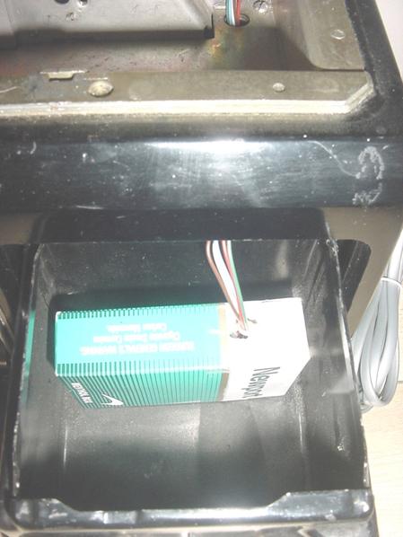
Figs. 6a, 6b, and 6c show the harness as it leaves the network sitting in the coin can. The harness runs up through the hole in the tray and into the body of the phone - in this case a Western 210G.
Since the 210G and 212G are post-pay phones, any deposited coins pass through the hopper and fall into the coin can. Theres no chance of the hopper getting clogged and the coins overflowing into the wiring of the phone. These hoppers can be left as is.
A standard modular cord was used to connect the payphone to the phone line. It runs through the oblong hole in the back and under the strain relief of the handset cord.
Fig. 6a The completed assembly sitting in the coin can.
Fig. 6b The harness running through the tray and into the phone.
Fig. 6c
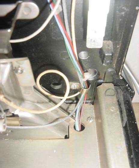
Shows the harness and modular cord wired inside the phone. I purposely positioned the harness in front of the phones parts to make it easier to follow the wiring. The proper position of the harness is shown in Fig. 8. The wiring should be away from the intake of the hopper and the back of the coin track when the phone is assembled.
____________________
Western Electric Pre-Pay Model 233G and 234G
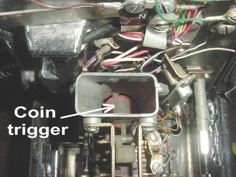
The harness wiring for the 233G and the 234G* is identical to the 210G and 212G shown above. However, both the 233G and 234G* have pre-pay hoppers that hold deposited coins. Since you dont want the coins to fill the hopper and overflow into the wiring, the coins should be routed out of the phone. You do this by locking the hopper in the refund position.To lock the hopper, push back the spring-loaded front of the coin relay and keep it in that position with a piece of stiff solid wire wrapped around the frame. A small plastic part called the coin trigger (located in the throat of the hopper) must be pushed down before the front of the coin relay will move all the way back. Refer to Figs. 7 and 7a. Any coins put in the phone will now fall into the return chute.*Later versions of the 234G had plug-in tops and (sometimes) internal ringers. These added parts changed the location of terminals. Depending on the vintage of your 234G, some wire lengths may be a little long.
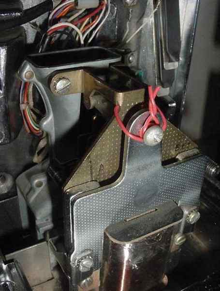
Fig. 7 The pre-pay hopper and coin relay locked in the refund position.
Fig. 7a The coin trigger in the down position.
____________________
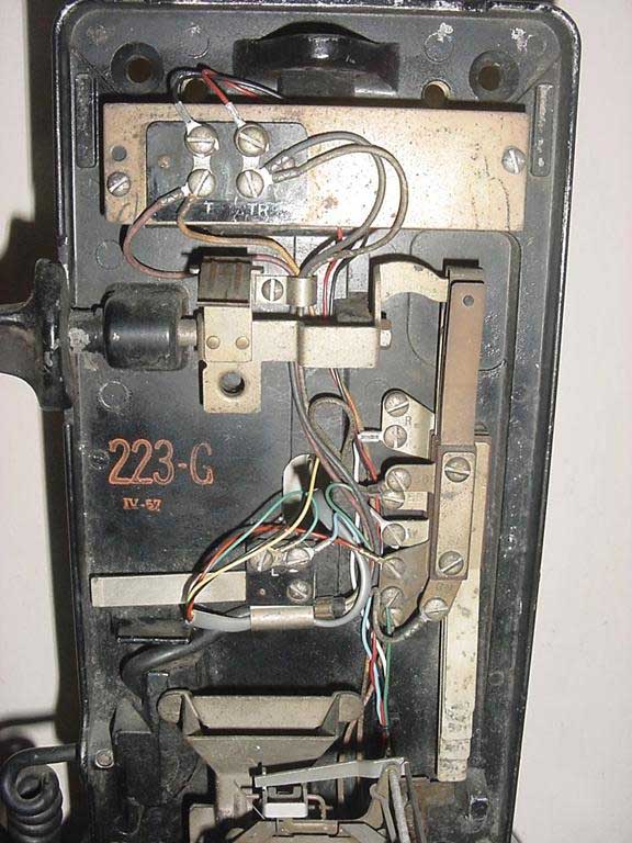
Western Electric Pre-Pay Model 223G
Wiring the Western 223G is slightly different than the models described above. The (L) terminal in a 223G is a separate assembly in the center of the phone. Its not on the terminal board at the top. The length of the (C) wire that connects to it is 16 inches.
The wire lengths are:
B, R, = 23 inches C = 16 inches RR = 16 inches GN = 14 inches
Aside from the location of the (L) terminal, wiring the network and phone line to a 223G is identical to a 233G and 234G.
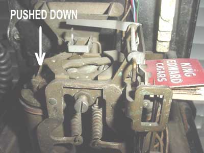
The 223G was the last pre-pay three slot payphone to use a double coil coin relay. Like the other pre-pay phones, the coin relay must be locked in the refund position.
Lock the relay in the refund position by pivoting the armature to the left, then jamming a piece of cardboard between the top of the right hand electromagnet and the bottom of the armature. Refer to Fig. 8a.
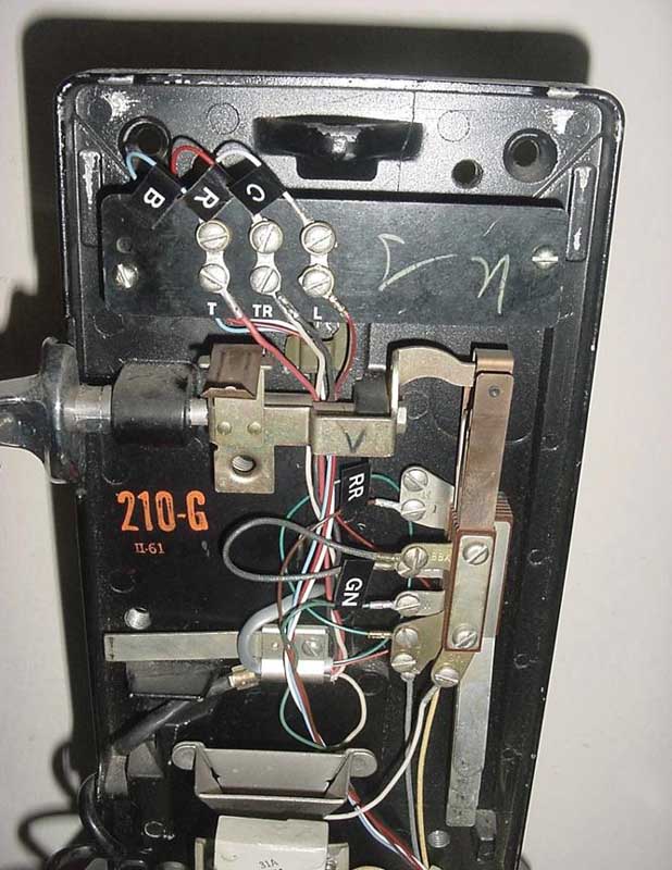
Fig. 8 Shows the harness installed in the phone. The (L) terminal board is mounted on the same screw as the handset cord strain relief.
Fig. 8a
Shows the double coil coin relay locked in the refund position. The matchbook is an exaggeration to show the position of the cardboard.
____________________
Northern Electric Post-Pay Model QSD-3A
Wiring a QSD-3A to the network and the phone line is different than the models weve discussed. The path of the harness is the same; the differences are the wire lengths and the location of the terminals in the payphone.
These are the wire lengths:
B, GN, C, = 23 inches R = 16 inches RR = 10 inches
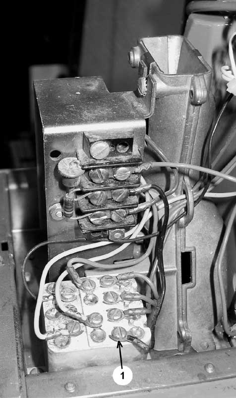
Fig. 9 shows the connections of the network and the phone line to the QSD-3A. Notice the (RR) wire from the harness is connected to terminal #1 of the relay box, mounted to the right of the hopper. Fig. 9a is a close-up of the #1 terminal.
Since the QSD-3A has a post-pay hopper (like the 210G and 212G), it can be left as is.
The Northern Electric QSD-3A is polarity sensitive. Thats one of the reasons it functioned as a post-pay phone back in the day. If your newly wired phone wont work, reverse the tip and ring wires of the modular cord in the phone.
Fig. 9
Shows the harness and phone line wired to the QSD-3A.
Fig. 9a Shows the location of the #1 terminal.
____________________
Special thanks to Dave Hunter for the photos of the Northern Electric QSD-3A.
Click the link below to visit his amazing website.
The History of the Telephone on Prince Edward Island
____________________
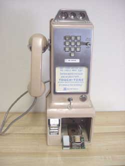
Western Electric Touch Tone Pre-Pay Model 1234G
The wiring of the 1234G is dense compared to the other models. To keep our wiring as neat as possible, only run the (RR) lead of the harness through the hole in the tray. Then, remove the 1A steel plate screwed to the back of the phone. The remaining wires are run out of the back casting through a hole in the vault compartment. Refer to Fig. 10b
Run these wires up the center on the outside of the phone and into the oblong hole. That brings all the wires (except RR) back into the phone in the center of the back casting. Reinstall the 1A plate and the wires that run outside are hidden.
This path for the harness prevents interference with the plug- in cable, when the top is put on the phone.
The wire lengths are:
B, R = 23 inches C, GN = 16 inches RR = 11 inches
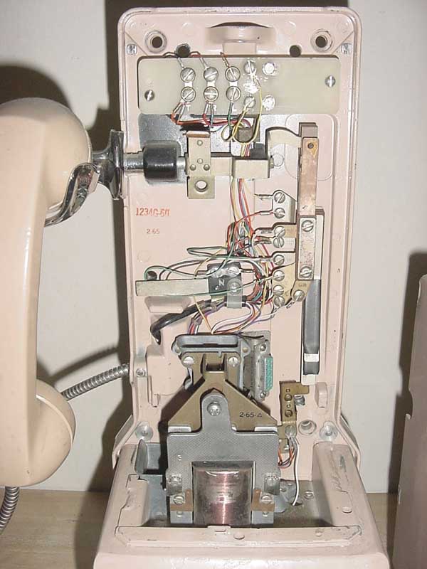
Fig. 10 shows the connection of the harness inside the phone.
Figs. 10a and 10b show the wire routing. Fig. 10 Shows the connections of the network and phone line in a 1234G.
Fig. 10aShows the connections and routing of the harness in the phone.
Fig. 10b Fig. 10c
Notice that four of the harness wires go through the hole in the back, and one goes up through the tray.
Like the other pre-pay phones, the coin relay in the 1234G must be locked in the refund position. Scroll up to Figs. 7 and 7a for details.
I used a Contempra network in this phone. Its larger than the ITT unit, but electrically identical. Unfortunately, it wont fit in the flip top cigarette box. Ill wrap cardboard and tape around it (again). I took it off to take the pictures. Not very pretty, but it works.
A modular cord was used to connect the payphone to the phone line.
Like all first generation Western Electric 10 button Touch Tone phones, the 1234G is polarity sensitive. If the phone doesnt generate tones when you push the buttons, reverse the tip and ring of the modular cord in the phone.
____________________
Alphabet Soup
If you look at a list of all the 200 series 3 slot payphones made by Western Electric and the corresponding Northern Electric models, youll see there are dozens of them. All the model numbers have an alphabet soup of different letters after them.
The information for the six models covered here is enough to wire a network in all of them. You may find a phone where a terminal was moved because of a special modification. Worst case, this will only change the length of the wiring. ____________________
What About The FCC?
I told the doctor I broke my leg in two places. He told me to quit going to those places.
(Henny Young 1906-1998)
Next question!
____________________
Where Do I Find Parts?
If your junk box is telephonically challenged, I suggest you contact the House Of Telephones.
http://www.houseoftelephones.com/
House of Telephones, now Old Telephone Works has the networks, modular cords, multi-colored wire and solder lugs in stock. I think youre on your own as far as the flip-top cigarette box is concerned. Mention this article so hell know what youre doing and exactly what you need. ____________________
|
|